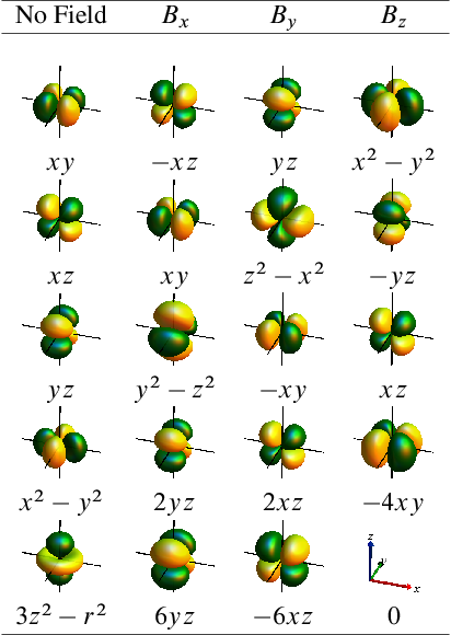
[Home] [GRP] [RES] [PUB] [ETC] [LEC] [S/W]
 

Orbital Rotation Models for NMR Parameters

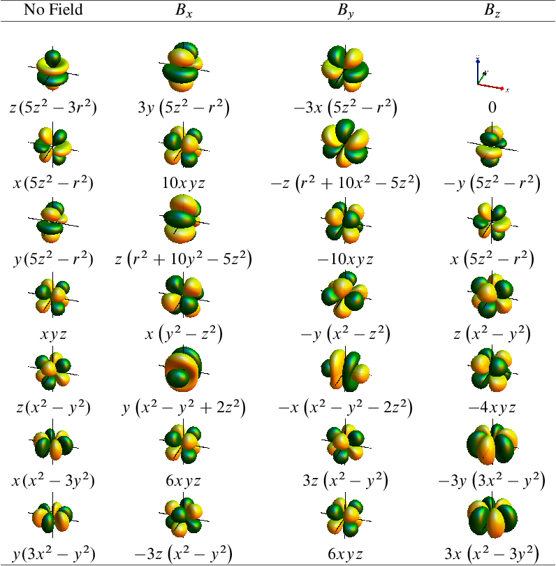
The sign and magnitude of magnetic properties such as NMR parameters can sometimes be rationalized with the help of ‘orbital rotation’ models. For an example, see this page explaining the substituent effects on the carbon NMR shifts in substituted benzenes. The idea behind such models is the following: An occupied orbital may contribute to the field-induced magnetic moment in a molecule if the action of the quantum mechanical magnetic field (‘B-field’) operator B^ on the orbital results in a function that can overlap well with another unoccupied orbital in the molecule.

This statement has its origin in terms that appear in the NMR shielding tensor expression, for example, when written in a molecular orbital theory framework [1]:

φunocc|B^|φocc
(1)

The integral measures the overlap between an unoccupied molecular orbital (MO) φunocc and the function B^φocc that is obtained from acting with the B-field operator on an occupied MO. The quantum mechanical B-field operator is proportional to the angular momentum operator L^ and has three vector components, for the x, y, and z direction. In simple models, one considers a representation of the molecular orbital in a minimal basis of so-called atomic orbitals (AOs).

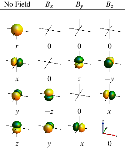
Because of the relation to the angular momentum operator, the action of the B-field on an AO typically resembles a rotation of the AO. Below are Tables with worked-out results for s, p, d, and f orbitals, for magnetic fields in x, y, and z direction. A factor of i2c has been omitted from the magnetic field operator.

s and p orbitals:
The graphics shows a table with 4 rows and 4 columns. The column headers are
from left to right: ’No Field’, Bx, By, Bz. The latter 3 indicate the direction of a
magnetic field. The 4 rows show 2s, 2px, 2py, 2pz atomic orbitals as green/yellow
isosurface lobes. Column 1 corresponds to the orbitals absent a field. The other 3
columns show isosurfaces of the functions that, up to a constant factor, represent
how the relevant orbital in column 1 of the same row is perturbed in first order by a
magnetic field in that direction. The polynomials in x, y, z defining the atomic
orbitals and their perturbations are also shown. Some of the table entries
are empty save for the coordinate axes. This indicates that the resulting
perturbation of the orbital vanishes. The bottom right entry of the table has a
zero function, too, but instead shows a graphic with the orientations of
the 3 axes of the Cartesian coordinate system, labeled and colored (x =


red, y = green, z = blue), as used for all of the other images in the table. d orbitals:
The graphics shows a table with 5 rows and 4 columns. The column headers are
from left to right: ’No Field’, Bx, By, Bz. The latter 3 indicate the direction of a
magnetic field. The 5 rows show the 3d atomic orbitals xy, xz, yz, x2-y2, and 3z2-r2
(’z2’) as green/yellow isosurface lobes. Column 1 corresponds to the orbitals absent
a field. The other 3 columns show isosurfaces of the functions that, up to a constant
factor, represent how the relevant orbital in column 1 of the same row is perturbed in
first order by a magnetic field in that direction. The polynomials in x, y, z defining
the atomic orbitals and their perturbations are also shown. Some of the table entries
are empty save for the coordinate axes. This indicates that the resulting
perturbation of the orbital vanishes. The bottom right entry of the table has a
zero function, too, but instead shows a graphic with the orientations of
the 3 axes of the Cartesian coordinate system, labeled and colored (x =
red, y = green, z = blue), as used for all of the other images in the table. f orbitals:
The graphics shows a table with 7 rows and 4 columns. The column headers are
from left to right: ’No Field’, Bx, By, Bz. The latter 3 indicate the direction of a
magnetic field. The 7 rows show the 4f atomic orbitals z(5z2-3r2), x(5z2-r2),
y(5z2-r2), xyz, z(x2-y2), x(x2-3y2), and y(3x2-y2) as green/yellow isosurface lobes.
Column 1 corresponds to the orbitals absent a field. The other 3 columns show
isosurfaces of the functions that, up to a constant factor, represent how
the relevant orbital in column 1 of the same row is perturbed in first order
by a magnetic field in that direction. The polynomials in x, y, z defining
the atomic orbitals and their perturbations are also shown. Some of the
table entries are empty save for the coordinate axes. This indicates that
the resulting perturbation of the orbital vanishes. The top right entry of
the table has a zero function, too, but instead shows a graphic with the
orientations of the 3 axes of the Cartesian coordinate system, labeled and colored
(x = red, y = green, z = blue), as used for all of the other images in the
table.

Orbital rotation models for p orbitals have been in use in organic chemistry for quite some time to help rationalize trends in observed NMR chemical shifts [2, 3]. We have developed orbital rotation models for metal complexes with occupied d and f orbitals [4, 5]. For instance, by considering how the action of a magnetic field on the nonbonding 5d orbitals in Pt(II) and Pt(IV) complexes results in an effective magnetic coupling with unoccupied metal-ligand σ orbitals rationalizes the large chemical shift difference between 195Pt chemical shifts for the two oxidation states [4].

References

[1]   Autschbach, J. The calculation of NMR parameters in transition metal complexes. In Principles and Applications of Density Functional Theory in Inorganic Chemistry I, Vol. 112; Kaltsoyannis, N.;  McGrady, J. E.,  Eds.; Springer: Heidelberg, 2004.

[2]   Grutzner, J. B. Chemical shift theory. Orbital symmetry and charge effects on chemical shifts. In Recent advances in organic NMR spectroscopy; Norell Press: Landisville, NJ, 1987.

[3]   Wiberg, K. B.;  Hammer, J. D.;  Zilm, K. W.;  Cheeseman, J. R. J. Org. Chem. 1999, 64, 6394-6400.

[4]   Autschbach, J.;  Zheng, S. Magn. Reson. Chem. 2008, 46, S48-S55.

[5]   Moncho, S.;  Autschbach, J. Magn. Reson. Chem. 2010, 48, S76-85.

© 2011 – 2025 J. Autschbach. The material shown on this web page is in parts based on the results of research funded by grants from the National Science Foundation [NSF, grants CHE 0447321, 0952253, 1265833] and educational projects supported by these grants. Any opinions, findings, and conclusions or recommendations expressed in this material are those of the author and do not necessarily reflect the views of the National Science Foundation.